Christmas tree (solder kit)
Add a festive xmas tree to your desktop or hang it on the real christmas tree as a decoration! This DIY solder kit is proven through annual workshops at Oslo’s largest Makerspace and Hackerspace and is a soldering favorite among the members and other workshop attendees.
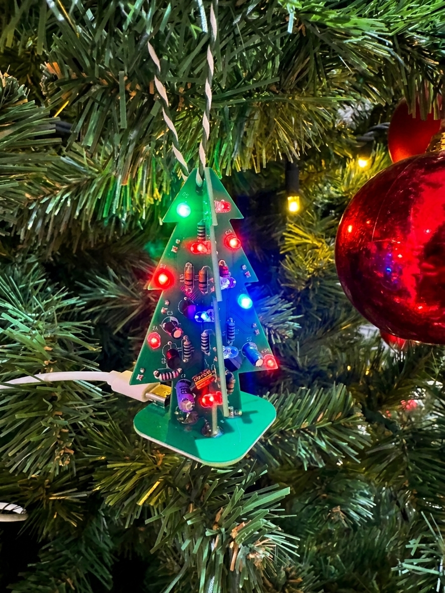
Want to improve your soldering skills and have some fun along the way? This kit is advanced enough that you’ll have unlocked a new skill once finished! You will know exactly how much solder to feed and apply to a solder joint and you can separate a good from a bad connection. When finished, this is a really impressive and charming kit that you can be proud of. We have worked hard to make the kit as easy to use and it solves many issues we have seen with similar kits.
An experienced person soldering will take just above an hour to assemble. A complete beginner will take about 2.5 hours to assemble. We have formerly use similar kits, but these come with significantly more to solder points, poor instructions, bad assembly experience and very variable component quality. This kit was created to solve these specific challenges to make it the perfect kit for christmas workshops in electronics. This kit is a fun and xmas themed activity for student groups, the office, with friends or for anyone wanteing to get better at soldering.
The kit provides a great for a single person, but it’s also used for soldering workshops with 10-12 attendees. Just put on the right music to get you in the mood and start soldering while watching the instructive video in the background. This version of the kit has enough soldering practice that by the end, even complete beginners will know intuitively exactly how much solder to apply, how long to hold the soldering iron to the joint and so on.
As with many of our DIY products, we also provide the full schematics for the kit so you can learn from that.
When soldering any through-hole electronics kit, you should start soldering the lower parts first and save the taller parts for last (or they will be in your way). Start by soldering the the resistors. Be sure to put them in the clearly marked positions. If you are unsure which resistors are 1k and 10k, use a multimeter to measure. It is however easy to spot since there are more 1k resistors in the kit than the 10k resistors. The resistors can be soldered in any orientation.
We recommend doing only a few components at a time and to finish one part of the tree before the other. We also recommend testing the both halves of the tree before soldering them to the foot. To test a single tree-side, plug in the USB cable and just hold the tree onto the foot to test. Do not solder the parts together until they are all tested, or it will be very difficult to take them apart. If something does not work, just check out the troubleshooting section.
Resistors
You should start by soldering a single resistor. Bend the legs on each side 90 degrees and slide the resistor in place. As you do this, double check that you did not put the 1k resistor in a 10k position and vice versa. Pust the resistor all the way in, so the legs are sticking out on the back. Bend the legs to any side, to lock the part in place. You assemble the components on the side with explanatory silkscreen and apply solder on the other side. Flip the board over to start soldering.
Be sure to clean the tip of the soldering iron well. A black tip is oxidized and will not attract solder. Use either a cleaning spunge – or even better – use a bowl of copper shavings made specifically for soldering. The incorrect way to solder is to apply the solder to the soldering iron and then try to smear it off. This will not work and will cause the project to fail.
Instead, you should apply a tiny droplet of solder to the tip. This hepls with heat transfer. Use this droplet to heat both the hole and the component leg. If you only heat the hole or the leg, you will get a poor connection (cold solder joint), so be sure to heat both. Feed solder onto the solder joint until you have a tiny “mountain-top”.
You should fill the entire hole and the surrounding ring, without leaving a big blob of solder. A tiny, pointy mountain top is what we are aiming for. Once both legs are soldered, get a flush cutter to snip off the legs just before the solder joint. If you don’t have a flush cutter, you can use any wire cutter, but try to not leave much wire sticking out since that can cause shorts.
Once you are happy with the first resistor, solder the remaining resistors. You could insert all resistors and then solder, but that will usually cause a mess. We highly recommend inserting maximum 3-4 components before you solder them. Use this soldering procedure for the remaining parts.
LEDs
After the resistors are assembled, you really have to pay attention as the remaining components must go in the correct way. Next come the LEDs. If you look at a single LED, it has one long and one short leg. The long leg should be towards the top of the tree. The short leg should be towards the bottom of the tree. Insert the first LED while observing carefully where the long and short leg goes. On the back of the PCB – bend the legs to the sides on the back and solder each joint. Make sure there is no connection between the two legs. Cut the legs off and solder another LED.
The tree looks the best if you alternate what side you put the LEDs on. If you look at the silkscreen, you can see what side we suggest putting the LEDs on. Soldering the resistors are the most time consuming part of the project, but also where the repetition makes you good at soldering.
Transistors
The transistors have 3 legs sticking out of a black plastic package. If you inspect one of them, you’ll see that the black plastic has a straight side and a curved side. On the stright side, there will be some text describing that this is a S9014 transistor. Be sure you insert the transistor so the straight and curved sides match the orientation on the silkscreen. If you rotate this part the wrong way, the tree will not work.
To insert the transistor, you will need to bend the legs slightly. Don’t worry about this. Parts like this are made to be bent a little and there are extra parts in the kit if you happen to bend too much.
Capacitors
Just like the LEDs and Transistors, these must go in the right way. Hold one of them up. They look like a “can” and they all have a stripe going down the side with minus-signs on them. The leg closest to that side is the negative leg (the minus). The other leg is the positive side (the plus). You can also note that the length of the legs are different, just as on the LEDs. Insert the capacitors and ensure that the short/negative leg goes into the hole marked “-” and the long/positive leg goes into the hole marked “+”. Flip around, bend the legs and solder. You might want to solder this part so it’s flat on the PCB, to make it easier to slide the two halves together later, but it’s not required.
Testing before assembly
As mentioned before, we highly recommend testing each half of the tree before assembling. To test a single tree-side, plug a USB cable into the foot and insert the tree into the slots. It will only go in one way. Just hold the tree onto the foot. You might have to tilt the foot a little to get contact. If something does not work, just check out the troubleshooting section.
When you have soldered and tested both sides, it’s time to assemble. Slide the two halves together. We have done what we can to avoid collisions, but there is often something in the way the first time you try this. Keep in mind that there are two orientations the pieces fit. One will be easier than the other. Also remember that the transistors can be bent safely towards the circuit board surface to let the tall capacitors side past.
Once the two parts are fully combined, find the foot of the tree. Disconnect the USB cable when soldering, or you can create a short and in the worst case even destroy the USB ports if they are not well built. Rotate the foot until the PCB’s slide into place. Only one orientation is correct, so be sure to rotate until both halves fit into the matching hole on the foot.
Place the foot on an even surface with the tree halves in position. At the foot, you should see one hole for each pad. The holes should be close to flush with the christmas tree foot. Solder the first of the foot-joints by heating one of these holes from one side and feeding solder through the other.
3 x Circuit boards (Top, Bottom, Foot, Lead free)
26 x Animated LED’s (Red, Green, Blue)
9 x 1k Resistors (2 spare)
8 x 22uF Capacitors (2 spare, in festive colors)
8 x S9014 Transistors (2 spare)
7 x 10k resistors (2 spare)
1 x Schematic drawing & instructions
Online instructions and assembly video. The kit has just above 110 solder joints to make. It really looks impressive and you will feel accomplished when completing the kit, since you have created something and learned to solder along the way. For young kids with a limited attention span, we recommend a Snowman kit with only 16 solder points instead.
This kit is used annually at the Bitraf Makerspace and Hackerspace as well as other places. We do offer a premade slide deck that you can use to organize the workshop as well as an assembly video that we will typically put on a loop once the slides are done.
The best setup is to provide a cosy atmosphere, but to not supply snacks. When soldering, you will get metal particles on your fingers that will then go into any food the participants consume. The slide deck starts with a warning about the dangers of leaded solder and a reminder to wash your hands before eating anything. While leaded solder is much easier to use, lead free solder is safer. We do typically mention how important it is to wash hands multiple times during the workshop.
In our experience, there is enough solder points per kit to warrant one soldering iron per attendee. You can however let two persons share both a soldering iron and flush cutters since you will typically alternate inserting components, soldering and cutting component legs.
We highly recommend using copper solder balls (flux coated copper/metal shavings) rather than spounges. These clean significantly better the a sponge and it also does not thermally shock the soldering tip.
If there is less focus on inserting components the wrong way, there will be more errors. We recommend that the workshop organizer solder up one kit in advance to have something to compare against when something is wrong. A visual reference is significantly easier when troubleshooting and it also looks inspiring to the attendees.
This kit is an improved version of a cheaper Chinese kit that we used for several years at Bitraf in Oslo. The quality has become significanyl worse over the years to the point where parts were missing and they did not fit. In 2025, a workshop failed completely due to poor parts quality, so we decided to make a better kit.
The end result is a product that has the following advantages over the cheaper kits:
– Connecting the the parts is significantly easier due to smarter parts placement and better tolerances.
– All parts in the kit are verified before kitting
– The kit has no screws or mechanical parts
– USB Type C connector is presoldered
– LED symbols are placed on both sides of the PCB, making for a prettier tree
– Only 112 solder points compared to 136 on the old kit, saves about half an hour of workshop duration
It is close to impossible to assemble the kit incorrectly. This was one of the most annoying things to resolve during workshops, since the old kit made it possible to connect GND and 5V if parts were incorrectly placed. This kit solves this by using different size slots, so the parts only go in the correct way.
A single LED or two isn’t lighting up
Most likely, it was inserted in the wrong orientation. Use a “solder pump” on a heated pin. If you heat the pin properly and hold the solder pump at the right angle, you will remove all the solder from the hole. This might take some practice.
If you do not have a solder pump, you can carefully pry the LED off using pliers while heating one leg at a time. Be careful to not touch the circuit board since you could easily damage it. Replace it with a spare part.
Parts of a circuit does not light up
Start by going over the resistors. Make sure you followed the instructions carefully and put 1k resistors in the holes marked 1k, and similar for the 10k resistors. Use the technique described above, using a solder pump to remove the incorrect components and move them to the correct position or replace them with spare parts.
Mixing resistors is the most common problem, but if they look correct, you have to inspect the orientation of the Capacitors and Transistors as well. These must all be in the correct orientation.
In extremely rare cases, a single component could be defective. To solve this, we supply spare parts with all our kits.
The board does not work at all
This has never happened in any of our workshops, but start looking for incorrectly oriented or placed parts as described above. If all looks to be in order, try using a different USB cable or even a different USB power source.