RadSense 1 Pinout
If you want to re-program your device to add extra features, you’ll need to know what features are connected to what pins. The ESP32 C3 has 14 pins that are all in use.
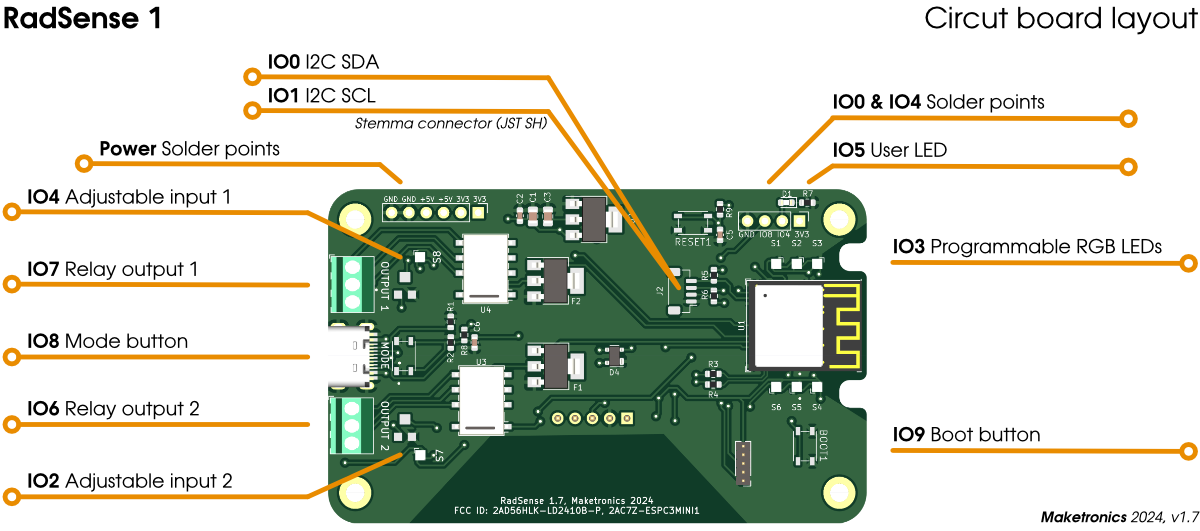
Pin table:
- IO0 – I2C SDA on the Stemma connector. Has 10k pullup.
- IO1 – I2C SCL on the Stemma connector. Has 10k pullup.
- IO2 – Potentiometer 2. Rotate with screwdriver to set distance for zone’s
- IO3 – NeoPixel data pin
- IO4 – Potentiometer 1. Rotate with screwdriver to set distance for zone’s
- IO5 – LED
- IO6 – Toggle relay 2
- IO7 – Toggle relay 1
- IO8 – Mode button. 10k pullup.
- IO9 – Boot button. May be used after the device has started
- IO10 – Interrupt on radar
- IO18 – USB Data –
- IO19 – USB Data +
- IO20 – RX to Radar
- IO21 – TX to Radar