Using RadSense 1 with Arduino
At Maketronics, we believe in giving access to all the information needed to augment or hack the software your device comes with. The RadSense sensor is based on a popular microcontroller from Espressif that is called ESP32 C3. In addition to measuring signals and turning things on/off, the device also has Wifi and Bluetooth connectivity. The device is fully working out of the box, but if you do want to update the firmware on the device or maybe even reprogram it to do new things, this tutorial will get you started.
Downloading the software you need
Software that is controlling hardware is usually referred to as “firmware”, since it’s in the hardware itself. To update the firmware on your RadSense 1, you’ll need a computer with an internet connection and the accompanying USB C cable.
Start by downloading the latest Arduino IDE (Integrated Development Environment). The software is available for Windows, Mac and Linux and it’s free, but you are free to donate money if you want to during the download process. Follow the installation instructions and start the program.
Once the software start up, click the Boards button (1), type ESP32 into the search field (2) and install “esp32 by Espressif Systems” (3). This install process may take a few minutes – depending on the speed of your connection.
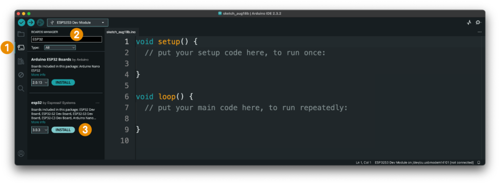
Software setup
The Arduino software makes it easy to work with many different microcontrollers, but we need to tell it which microcontroller the RadSense1 is based on. Click the Tools-menu > Board > esp32 >ESP32C3 Dev Module to select the board.
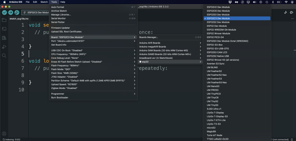
Next, connect the RadSense1 to your computer (No worries if you already plugged it in). Click the Tools menu and open the Port-menu. If you are on a Mac or Linux, it may look like below. Select the name containing “usbmodem”.

It will look similar on a Windows machine, but the port will be called COM1, COM2, COM3 and so on. It’s very likely that the port is the one with the highest number on a Windows machine. To be sure – if you unplug the RadSense1 device, you will see one of the listed ports disappear from the menu. That will be the port to use (once you’ve plugged it back in).
To use the Serial Monitor, you must also Enable the option for “USB CDC On Boot”. Without that, you will not be able to use Serial.print to debug your application. The steps above will repeat every time you open up a new document, so let’s do that next?
Using an example file
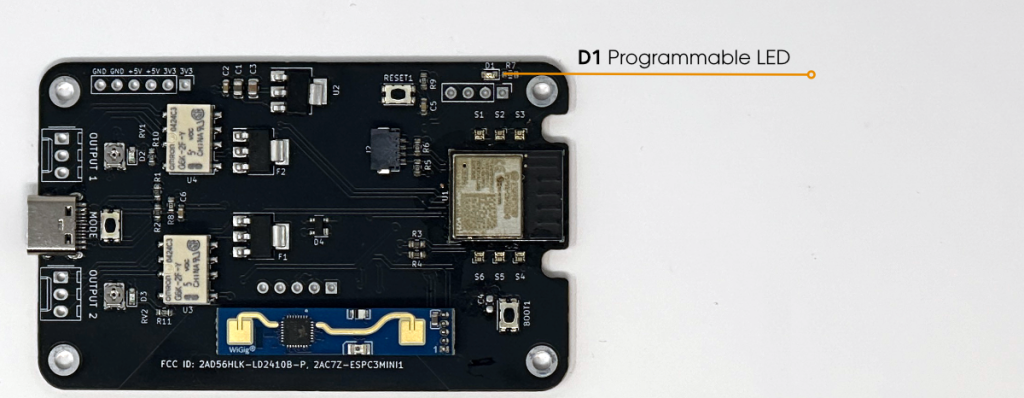
The Arduino IDE has several example files that let you test basic features. Let’s start by blinking the builtin LED. The LED is inside the box, so you’ll need to use the screwdriver that came with the kit to remove the lid to see it. Unscrew the four corner screws and you can see the electronics. At the top left, you can see the LED marked as D1 on the circut board. We’ll now make that blink. We recommend to use one of the screws to hold the circuit board firmly to the bottom of the box as you work with the device.
Select the menu File > Examples > 01. Basics > Blink. A new window opens up and you MAY have to repeat the steps above (Select the Board “ESP32C3 Dev Module” and the correct port). Once that is done, we’ll need to make a small addition to the example file by scrolling down and add a line of text after the grayed out text at the first 20-something lines of the file:
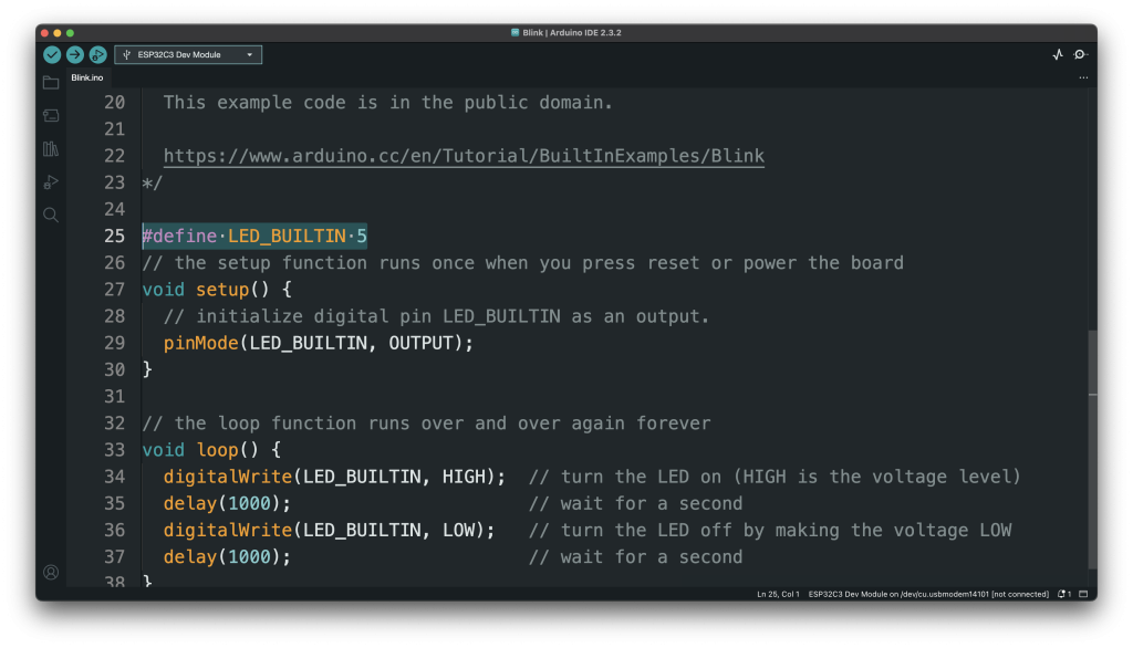
#define LED_BUILTIN 5
That’s all we add. Next it’s time to send this code to the device. In the top left corner, there are three buttons. Click the middle button with an arrow pointing right and the process to upload the code starts. In the lower part of the window, you’ll see a progress of the upload to the device. Once complete, you should see the LED blinking. You can adjust the speed of the blinking by changing the value in the parenthesis for the delay.
The above example only shows how to use a plain LED. The RadSense device also offers programmable LEDs, a button, two controllable relays, useful solder points for permanent connections as well as a STEMMA expansion port that will let you use a host of sensors, screens, motor controllers and other fun extras. We recommend browsing the selection of STEMMA development boards at Adafruit to see what’s available and possible! To explore other features of the device, have a look at our dedicated RadSense examples on GitHub. You may also find useful this pinout drawing that shows how everything is connected.
If you run into an error
1. Be sure you selected both the Board and the Port (as explained above).
2. Be sure that you did not delete any extra characters or added someting extra to the code. Computers are really finicky about this.
3. We have listed some of the most common errors and how to solve them in this post.
Restoring the original software
Every time you upload a new software to the device, it will replace what’s on the device. If you want the device to be just like when you purchased it, you’ll need to uload the same code that we ship the device with. This code is publicly available at this url https://github.com/jenschr/Radsense-1
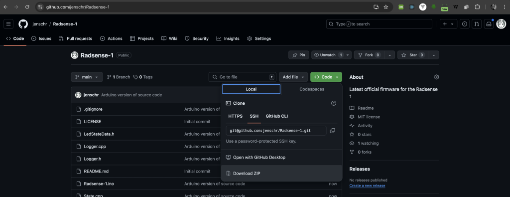
Unless you know what Github is, just click the green Code-button to reveal the link to download all the required files as a ZIP archive.
- Unzip the files
- Open the file “Radsense-1.ino” by double-cliking it. This should open the Arduino IDE with all the required files.
- As above – select the Board “ESP32C3 Dev Module” and the correct port

Once that library is installed, delete the text in the library search field and type “Adafruit Neopixel” and install that library as well. Now we should have everything ready. Press the Upload button (middle button at top left of the Arduino program, with an arrow pointing right). This will fully restore the firmware.
Please note that if you are one of the early adopters and the circuit board inside the device has the version number 1.6 (under the radar), you may need to swap the values for “LED_PIN” and “IN2_PIN”. This only affects a limited number of users.