Make a Silent IoT alarm with Push Notifications
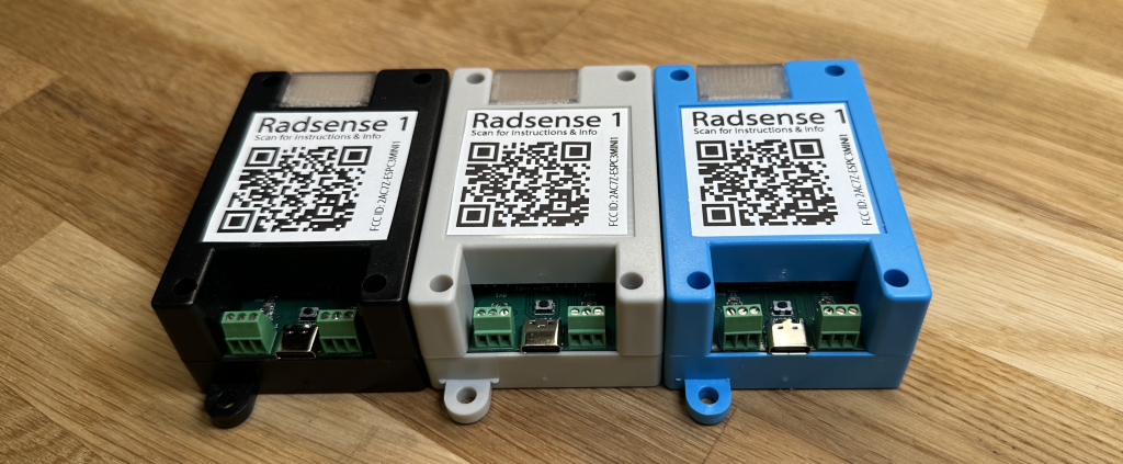
Want to know when someone is stealing your cookies? Or entering the server room or any other room you don’t want anyone to enter? Or do you want to know who keep unlocking that backdoor? What if you could get a Push Notification to your phone every time someone passed a certain spot. It’s quite easy if you use the RadSense sensor.

Based off an ESP32 C3 microcontroller, the device comes with some capabilities not used by default. Out of the box, the device requires absolutely no programming to be useful. You just attach the wires you want to control to the device and adjust the sensitivity. It’s really that easy. The device is however more advanced than just this and if you know a little programming and can use Arduino or VSCode with PlatformIO, you can extend the device to use features such as Bluetooth and Wifi.
Note: if you don’t have a RadSense device, you can still follow this tutorial if you have some variant of the ESP32 and a LD2410 millimeter radar breakout. You will need to make sure the radar is correctly connected and working before you do this tutorial, or you could just pick up a RadSense for simplicity 😉
In this tutorial, we’ll go over a code example that will use the brilliant service called PushSafer to send Push notification to any iPhone, iPad, Android, or Windows desktop device, Telegram, browsers (Chrome, Firefox, Edge, Opera & Yandex) and there’s even support for Windows mobile. The service can be used with an impressive selection of protocols, devices and programming tools:
This tutorial is based off their Arduino examples. First we’ll explain how the code works, then we’ll go over how to use it with the RadSense device for both Arduino and PlatformIO. The Pushsafer example is just one of several code examples for the RadSense device and if you want to go back to the original firmware, we supply that as well. We believe in open source and open hardware. If you buy it, you also own it and can do whatever you want with the device.
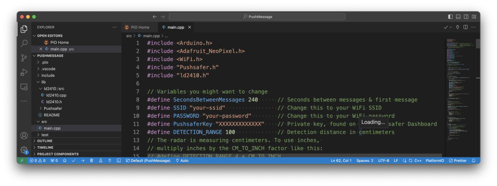
Let’s start by going over to GitHub to download the example files for making Push Notifications from your ESP32 based device. If you know GIT, just grab the files. If you don’t know GIT, just click the green Code-button and download the ZIP archive from the menu that shows up. Navigate to the downloaded files, select either Arduino or PlatformIO (based on your preference) and open the example file. For Arduino, the file we want to look at is in the “arduino/PushMessage” folder. The file you want to open is called “PushMessage.ino”. For PlatformIO, create a new Window (File > New Window) and then open the “platformio/PushMessage” folder (File > Open Folder). Then open the Explorer panel, browse to the “src” folder and open “main.cpp”.
How the code works
We’ll use the example file from PlatformIO since that has less comments and is easier to read. At the top of the file, there’s a series of include-statements. These are libraries that contain the features required by our code. If you use Arduino, you’ll need to install some of these manually. This is described in the comment at the start of the file. If you use PlatformIO, all the required support files will be installed for you – based on the contents of the “platformio.ini” file.
					#include <Arduino.h>
#include <Adafruit_NeoPixel.h>
#include <WiFi.h>
#include "Pushsafer.h"
#include "ld2410.h"
The next section contains a few variables that you’ll need to update for the code to work.
					// Variables you might want to change
#define SecondsBetweenMessages 240      // Seconds between messages & first message
#define SSID "your-ssid"                // Change this to your WiFi SSID
#define PASSWORD "your-password"        // Change this to your WiFi password
#define PushsaferKey "XXXXXXXXXXXXX"    // Private key, found on your Pushsafer Dashboard
#define DETECTION_RANGE 100             // Detection distance in centimeters
// The radar is measuring millimeters. To use inches,
// multiply inches by the CM_TO_INCH factor like this:
// #define DETECTION_RANGE 4 * CM_TO_INCH
Enter how many seconds you want between eash Push message. If you set a very low number of seconds, it’s easy to forget and you’ll use up all the free Push messages you get when you sign up for the PushSafer service. It’s not very expensive to buy 1000 more messages (1 EUR), but it’s better to set this number high. You also need to enter the SSID and Password so you can connect the device to your wifi.
Note that the radar works in centimeters, so if you’re American and think in terms of inches, just multiply inches by the variable named MM_TO_INCH as mentioned in the comment. To set the DETECTION_RANGE to 4 inches, change it like below:
#define DETECTION_RANGE 4 * CM_TO_INC
We also need to change the “PushsaferKey” variable, but we’ll do that later. Next up is a section of code that holds some constants (variables that normally should not be changed).
					// Constants
#define RADAR_SERIAL Serial1
#define MM_TO_INCH 25.4
#define SCL_PIN 1
#define SDA_PIN 0
...
Enter how many seconds you want between eash Push message. If you set a very low number of seconds, it’s easy to forget and you’ll use up all the free Push messages you get when you sign up for the PushSafer service. It’s not very expensive to buy 1000 more messages (1 EUR), but it’s better to set this number high. You also need to enter the SSID and Password so you can connect the device to your wifi.
					ld2410 radar;
Adafruit_NeoPixel *pixels;
WiFiClient client;

Pushsafer pushsafer(PushsaferKey, client);
unsigned long lastTimeMessageWasSent = 0;
Next up is the method that let us set the color of the programmable pixles. We’ve done it this way so that everything that has to do with the RGB pixels happen in one place, both creation of the NeoPixel object as well as setting and updating the color/brightness. This means that opposed to typical Arduino style code, we don’t make an Adadfruit_NeoPixel object at the start of the code. We just set aside space in memory for it using a pointer (*).
					void setPixels(uint8_t red, uint8_t green, uint8_t blue)
{
  // uncomment to never use LEDs
  // return;

  // if we don't have a pixel object, make one
  if(pixels == nullptr)
  {
    pixels = new Adafruit_NeoPixel(8, NEOPIXEL_PIN, NEO_GRB + NEO_KHZ800);
    pixels->begin();
  }

  // Set all pixels to the same color
  for(int i = 0; i < NEOPIXEL_COUNT; i++)
  {
    pixels->setPixelColor(i, red,green,blue);
  }
  pixels->show();
}
As you can see from the code, this also means that we are not accessing the LEDs using the typical dot syntax (pixels.setPixelColor) but instead use the arrow operator to the pointer. We check if an object has been made and if not, we’ll make one. This saves us from having to do this in the setup() function, making that look cleaner. Then we set the color. In this case, it makes sense since all the code for the pixels are in one place. In other projects, one might want to do this differently.
The RGB LEDs are perfect for debugging, but to make a completely stealthy device, you may not want any LEDs at all. To get this behavior, just remove the two slashes before the “return;” statement at the start of the method. That will make the device skip the remaining LED code and thus never initialize or used the LEDs at all.
Next up is the method that actually sends the message off to the PushSafer service. We’ll call this only if the radar has been triggered. It starts off by checking if enough time has elapsed. We do after all not want to receive lots of messages if nothing new has happened. If we have a wifi connection, we’ll then flash the LEDs in a bright White color (to know it was sent) and build the PushSafer object. You can customize the Push Message significantly with text, sound, URLs and images by changing the input-object, but test with these defaults before making any changes.
					void sendPushMessageIfItIsTime()
{
  if( millis() - lastTimeMessageWasSent > (SecondsBetweenMessages * 1000) )
  {
    if(WiFi.isConnected())
    {
      Serial.println(F("Sending push message"));
      setPixels(255,255,255); // bright white while sending!

      struct PushSaferInput input;
      input.message = "The sensor was triggered!";
      input.title = "Sensor triggered";
      input.sound = "48";
      input.vibration = "1";
      input.icon = "1";
      input.iconcolor = "#FFCCCC";
      input.priority = "1";
      input.device = "a"; // Must be set to 'a' for 'all'
      input.url = "https://maketronics.no/radsense-1/";
      input.urlTitle = "Open maketronics.com";
      // Check Pushsafer documentation for more options

      Serial.println(pushsafer.sendEvent(input));

      setPixels(0,0,0); // off
      delay(200);
    }
    else
    {
      Serial.println(F("Wifi not connected. Cannot send Push message."));
      setPixels(255,0,0); // bright red!
      delay(200);
      setPixels(0,0,0); // off
      delay(200);
    }

    // Update the last time a message was sent
    lastTimeMessageWasSent = millis();
  }
}
If all goes well, the pushsafer.sendEvent method will send your message off. If for some reason the Wifi isn’t connected, we’ll blink the LEDs in Red so we can understand what went wrong.
Next up is the Setup method. If you know Arduino-style programs, you’ll know that this is the first bit of code that runs just once. Here we setup everything and test that our devices work.
					void setup() {
  ...
}
The listing is a little long so we’re not showing it, but briefly explained we’ll initialize and test the radar, turn on the LEDs for debugging and log onto the wifi. If the radar fails, we’ll blink the LEDs in Red color. While logging onto Wifi, we’re blinking the LEDs Green. If Wifi does not connect within 10000 milliseconds (10 seconds), we’ll just skip ahead without wifi. This will prevent the messages from being sent, but will let you still play with the device if you don’t have WiFi available.
On Arduino systems, the loop() method will run forever after the setup() is finished. This is wher we do the actual detection. We’ve written this code so you can easily learn from it and tweak it. The first we do is to read() the radar. Without this, it will not update it’s readings. Then we test if any presence was detected at all. If not, we’ll turn off the LEDs completely.
The LD2411 radar can reliably detect persons that are up to 5 meters (16,4 feet) away from the device. It’s only at 3 meters (10 feet) it can report the approximate distance though, so you should not try to detect beyond that. Do keep in mind that since this is a readar, it will see through most walls. That’s the primary reason for limiting the distance, so we don’t get false positives. This also means that you could hide the sensor really well inside any non-metal object.
The LD2411 can detect both moving or stationary targets, so in our code we’ll use either of these (|| operator) to trigger the device.
					void loop() {
  bool wasRead = radar.read();
  if( wasRead ) // Only do updates if we could read the sensor
  {
    // This is the very simplest way to detect presence
    // It does not support any limiting of detection range
    // but it's very solid and fast
    if( radar.presenceDetected() )
    {
      // Only do something if within range
      int moving = radar.movingTargetDistance();
      int stationary = radar.stationaryTargetDistance();
      if( moving < DETECTION_RANGE || stationary < DETECTION_RANGE )
      {
        setPixels(0,55,0); // Pixels Green
        sendPushMessageIfItIsTime();
      }
      else
      {
        setPixels(55,0,55); // Pixels Pink
      }
    }
    else
    {
      setPixels(0,0,0); // Turn pixels
    }
    delay(50);
  }
}
If something is detected within the detection range, we’ll set the LEDs to Green and send the Pusn Notification. If not, we’ll set the pixels to pink, to show that we’re within the range that we can detect. If you don’t have a tiny break in your code, the Serial programming system will have a hard time setting the device into programming mode so at the end we’re adding a small delay. This won’t matter much for the detection since the device can only reliably do 10-15 measurements per second anyway.
There is one thing left to do for this to work and that’s to make a PushSafer account and get the value for the “PushsaferKey” variable.
Getting the PushSafer secret key
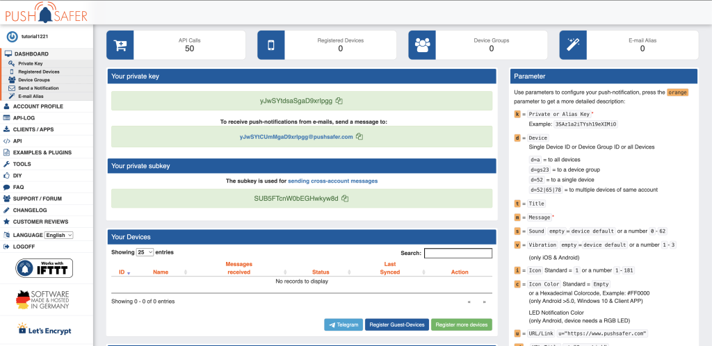
When you register a new email address, you’ll currently get 50 free Push messages from the PushSafer service. As mentioned, it’s not very expensive to get more than this and that is part of the reason why I like this service so much. Go to the PushSafer homepage and follow their guide to sign up. they’ll send you an email verification and then you can sign in. Once signed in, you’ll be greeted with a screen like this:

At the top of the screen, you can see your remaining API Calls (number of free notifications), the amount of registered devices and more. Below that is your private key that we need for our code. Click the copy-button to copy the key (“yJwSYtdsaSgaD9xrIpgg” in my case) and paste that into the “PushsaferKey” variable at the top of our code:
#define PushsaferKey "yJwSYtdsaSgaD9xrIpgg" // Private key, found on your Pushsafer Dashboard
If you previously added your wifi credentials, this is all we need for the code to work. If you at this point know how to use Arduino or PlatformIO, just do what you normally would do to uplaod the code. If you don’t know or run into problems, keep reading the instructions for either Arduino or PlatformIO below.
Uploading the code using Arduino
When you plug the RadSense into your computer, the Arduino IDE will correctly identify it as an ESP32 C3 device. Click the Board-selection Dropdown to be sure the device is selected. On a Mac or Unix machine, the Port name will look like in the picture below. On Windows it will be called “COMX” where the X will be a number (i.e. COM4).

To get the Serial port working on an ESP32 C3, we’ll need to enable “USB CDC On Boot. Click the tools Menu and scroll down to find the USB CDC setting.

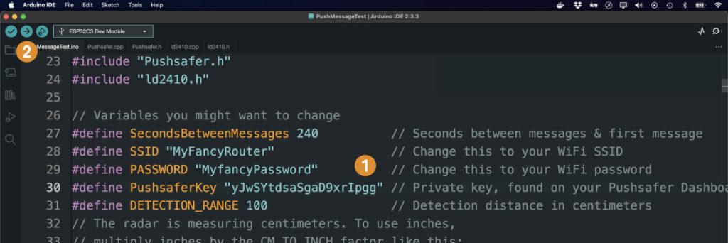
Next we make sure to have the required libraries installed. Open the Library Manager (1) and search for ArduinoJson (2) as below. When that is installed, search for Adafruit NeoPixel and install that library as well.

With both the ArduinoJson and NeoPixel libraries installed, you are ready to change the SSID, PASSWORD and PushSaferKey as explained above (1) and when you have those input, press the green arrow pointing to the right (2) to upload the code to the device.

Unless something goes wrong, the code should now be uploaded and working. Remember that the first message will only be sent after X seconds. This is very useful so the device is not triggered until you have left the room yourself. If you run into problems, check out our extensive Arduino Tutorial that also contains troubleshooting tips.
Uploading the code using PlatformIO
Start by creating a new Window (File > New Window). Next, you use “File > Open folder” to browse to the Pushsafer example folder that you already downloaded from GIT and unpacked.
With PlatformIO, most of the work above is done automatically for you since the hardware description and required libraries are defined in the “platformio.ini” file that comes with the project. This file is also where you’ll tweak if you are using a generic ESP32 and not a RadSense device.
					[env:esp32-c3-devkitm-1]
platform = espressif32
board = esp32-c3-devkitm-1
framework = arduino
build_flags =
	-D ARDUINO_USB_MODE=1
	-D ARDUINO_USB_CDC_ON_BOOT=1
	-D CORE_DEBUG_LEVEL=1
	-D ARDUINO_ESP32C3_DEV=1
lib_deps =
	adafruit/Adafruit NeoPixel @ ^1.11.0
    bblanchon/ArduinoJson @ ^7.2.0
Next, open the src/main.cpp file to update SSID, PASSWORD and PushSaferKey as explained above.

That’s all that is needed in PlatformIO. Upload the code to the device using the PlatformIO Upload command. If you are unsure about that, read our PlatformIO Tutorial for the full details on how to use this IDE.
A couple things to keep in mind with PushSafer
While the platform is easy to use, you may quickly use up the 50 free messages. As mentioned, it’s quite cheap for the ease of use. In the PushSafer web interface, you can set up more than one device to receive the alerts. These devices can be turned on/off as needed via the web interaface and you can add new devices by just scanning a QR code.
Click the image below to read about the Candy Crush project where Pushsafer really saved us!
Extending beyond PushSafer
The combination of a radar sensor with a powerful microcontroller with both WiFi and Bluetooth (BLE), you are certainly not limited to using only the PushSafer service. Based on the above example and other code you can find for the ESP32 family, you can extend the RadSense device to use virtually any Internet Of Things (IoT) and Industrial Internet Of Things (IIoT) service. Feel free to test it with IoT services and Dashboards such as IfThenThisThat (IFTTT), Thinger.io, ThingSpeak, AllThingsTalk, AskSensors and many more.

